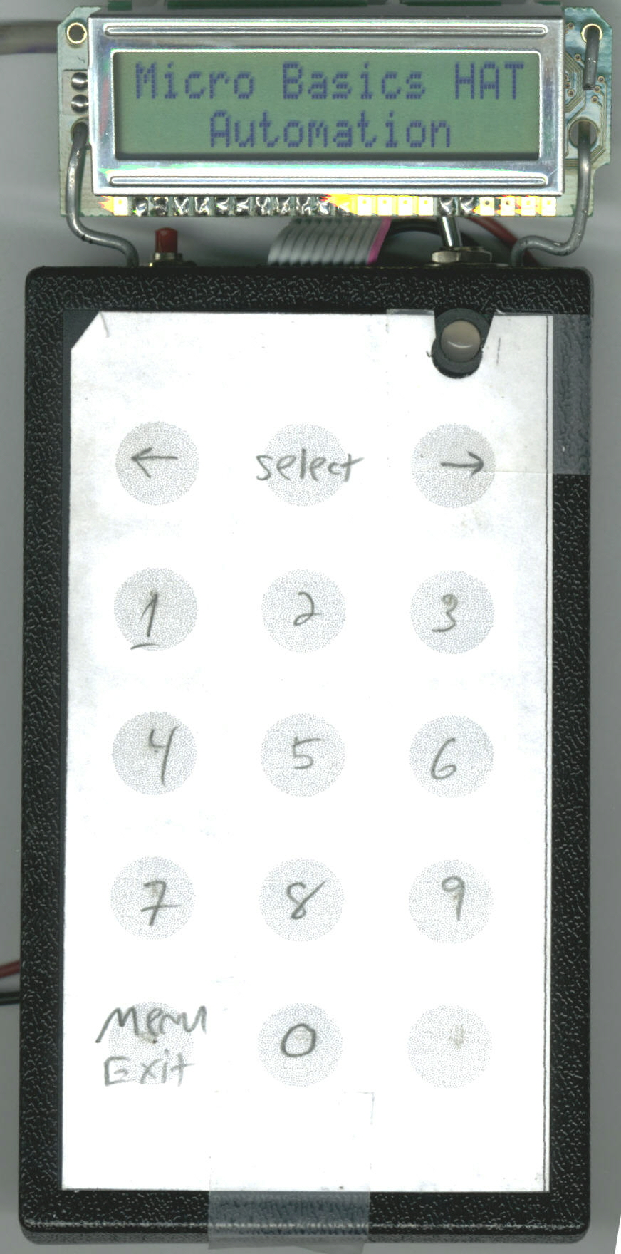
Face:
Note the bi-color LED on the top right of the keypad (Only shows power on) |
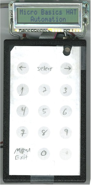
Click Here for Larger Picture (616KB) |
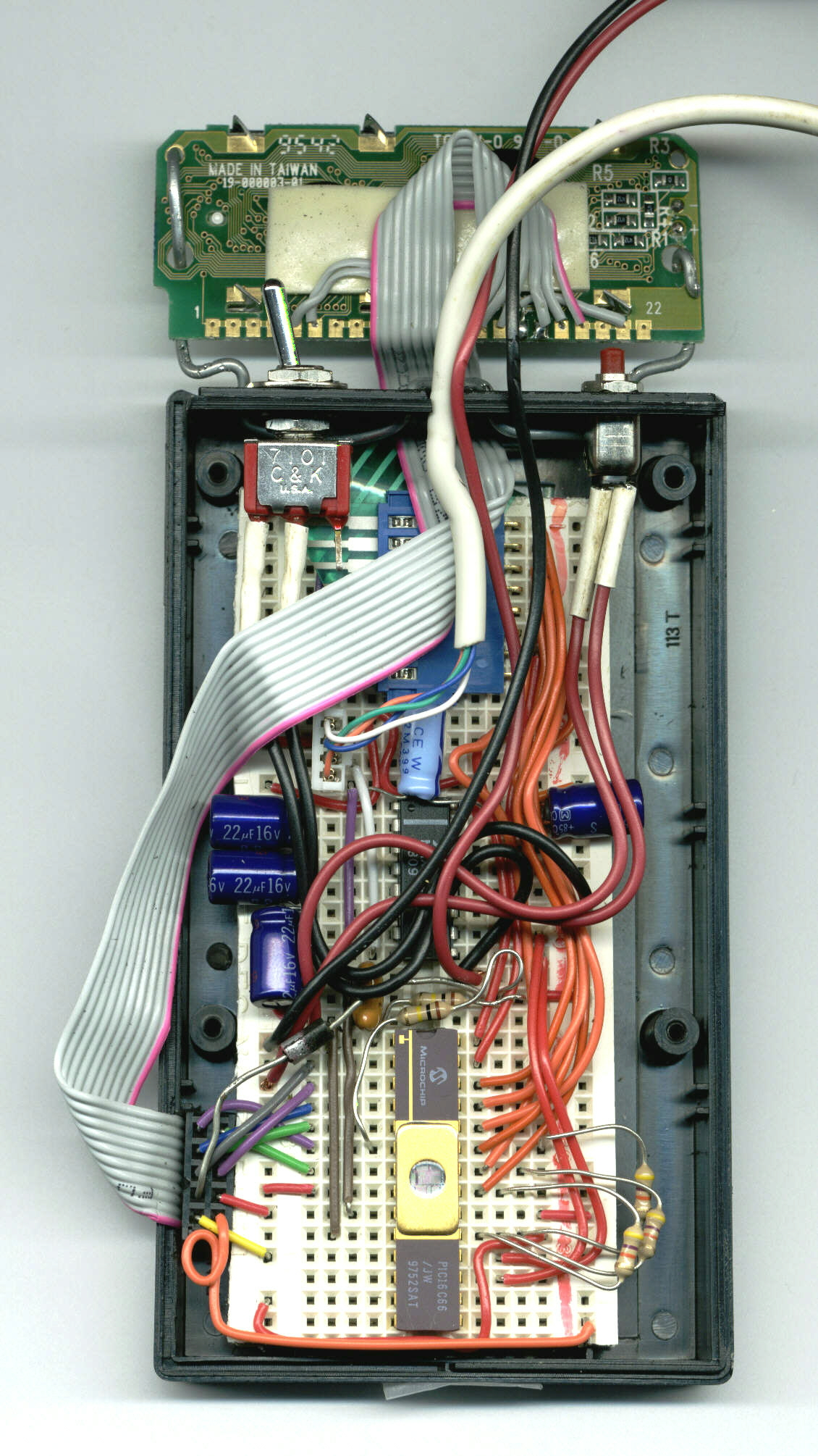
Inside the Rat's
Nest:
(Notes to the right) |
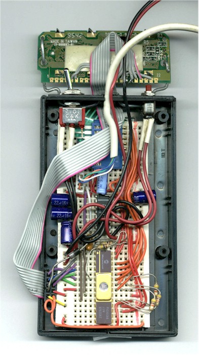
Click Here for Larger Picture (1.15MB) |
Power was supplied through the
red and black wires. The serial cable came from a mouse that had signed it's
organ-donor card. The LCD is soldered to 5/17ths (10 wires) of a
sacrificial floppy cable. |
| Note the power switch on the
top left and the reset button on the top right of the case. Also the wire (14 gauge,
I believe) supporting the LCD is threaded through the top. |
| The keypad cable connects to the board here
after a rather acrobatic twist. It ain't movin' again. The thermister is not in
this picture, but if it were, you'd see it just above and to the right of the MAX232 |
| The MAX232A resides here,
ultimately to be replaced by an RS-485 transceiver. The caps are way over-rated.
I just got the wrong parts. |
And, of course, the PIC 16C66.
You'll note the diode above and to the left of the chip which limits voltage to the
backlight. The resonator is just above and to the left of the chip as well.
The LCD cable ends up jammed between the breadboard and case.
The three resisters to the right are for the columns of the keypad, the one above the chip
is for PortA:4, which is a current sink, not source (TOCK1). |